

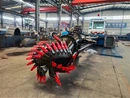

The draghead is the main dredging tool of a trailing suction hopper dredger. The trailing suction hopper dredger conducts dredging operations as a single - vessel. It is applicable to various types of soil except for rock and hard substrates. It is suitable for the capital construction and maintenance of dredging projects in offshore areas, seaports, and deep - water inland waterway channels. It is a dredger with high dredging performance and economic benefits.
Since the trailing suction hopper dredger emerged in Europe in 1880, it has developed rapidly. In recent years, the hopper capacity of some has reached over 10,000 m³, with a dredging depth of more than 30 meters, and it is equipped with modern devices such as electronic instruments. Since China introduced the "Kuaili" 500 - m³ self - propelled trailing suction hopper dredger in 1920, it has also developed rapidly in recent years. Since the 1970s, various types of trailing suction hopper dredgers with capacities of 4500 m³, 800 m³, and 1500 m³ have been manufactured. Currently, the largest one is the 6500 - m³ side - casting trailing suction hopper dredger introduced in the early 1980s.
With the development of the trailing suction hopper dredger, the draghead has also developed accordingly. Its main development directions are as follows:
Increase the dredging concentration of the draghead.
Reduce the drag - moving resistance of the draghead.
Dredge (cut) hard and compact soil.
Improve wear - resistance strength and reduce damage to the equipment.
Structure of the Draghead
Generally, a draghead consists of the following parts:
Suction Port: The lowermost part of the draghead contacts the riverbed, and the excavated sediment is sucked in from here. The area of the suction port depends on the suction pipe, usually three times that of the suction pipe.
Grid: A grid is installed on the opening surface below the suction port to prevent large debris from being sucked into the mud pump. The side - length of the rectangular holes of the grid should be 10% smaller than the size of the debris designed to pass through the mud pump.
Scraper Plate: Located at the lower part of the movable jaw plate, it serves to scrape and break the soil. To maintain a good fit with the mud surface, the front jaw plate is movable.
Flap Plates: Divided into two parts. The rear jaw plate is above the drag lip, and the front jaw plate is fixed to the suction pipe joint. The two parts are connected by an axle to prevent the excavated material from leaking out.
Drag Shaft: It is the pin connecting the two jaw plates, making the jaw plates flexible and enabling them to fit the riverbed during dragging.

Drag Plate: Located at the bottom of the drag shaft, it protects the draghead. In some cases, to prevent the drag plate from getting stuck, there is a weight below it. This weight is generally installed at the rear of the drag lip.
Safety Pin: There is a connecting safety pin between the suction part of the draghead and the pipe. When the drag - moving encounters an obstacle, the safety pin will break first to protect the draghead from damage.
Movable Cover Plate: An movable cover plate is installed on the upper part of the draghead. According to the soil type of the riverbed, it can be opened when necessary to supplement the water intake of the draghead and prevent the suction port from being "blocked" when dredging soft mud.
Protective Plate: Installed on the side of the draghead near the ship, it protects the ship's plate when the draghead is lifted or lowered.


